Interactive
See your hardware, not vague boxes
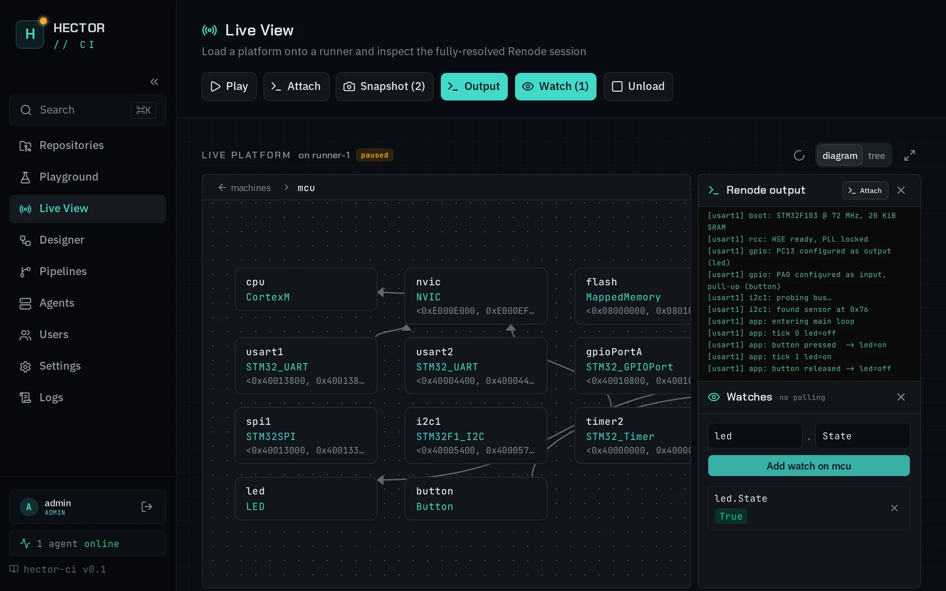
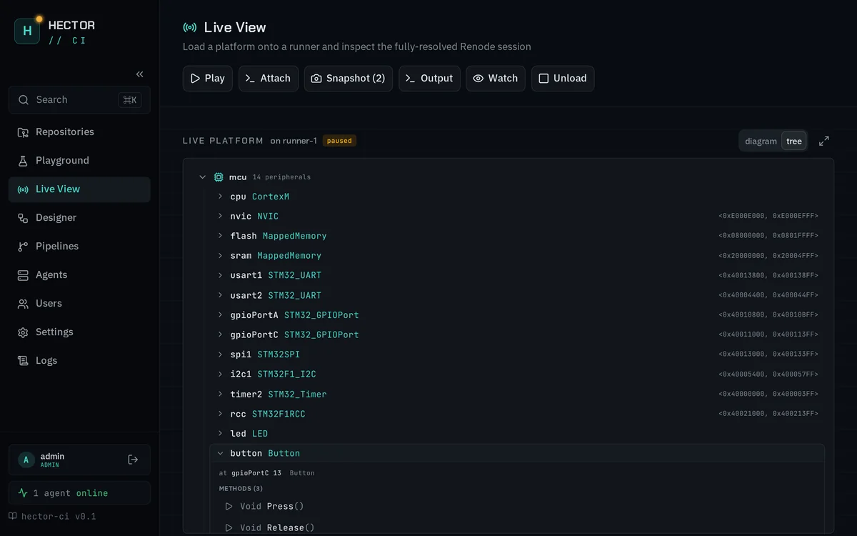
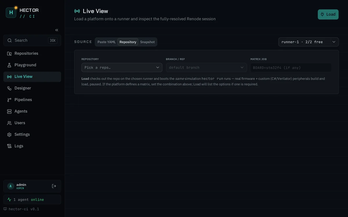
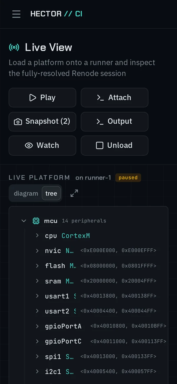
This is the platform diagram from Live View,
running right here — built from the stm32f103-full example that ships with the
CLI. Click the machine to open it, drag the blocks, drag the background to pan.
×N on a wire means that many individual pin or IRQ lines aggregated into one.
.hector.yamlthe source this diagram is built from — read only
version: "0.1"
renode_version: "1.16.1"

arguments:
  BIN: "https://dl.antmicro.com/projects/renode/zephyr-stm32f103-button.elf-..."

machines:
  blackpill:
    firmware: ${BIN}

    peripherals:
      # mcu — the complete STM32F103. An inert CombinedInput registered @ none:
      # it groups the MCU peripherals without touching the bus.
      mcu:
        type: Miscellaneous.CombinedInput
        at: none
        numberOfInputs: 1
        peripherals:
          flash:     { type: Memory.MappedMemory,        at: sysbus 0x00000000, size: "0x20000000" }
          sram:      { type: Memory.MappedMemory,        at: sysbus 0x20000000, size: "0x10000000" }
          nvic:      { type: IRQControllers.NVIC,        at: sysbus 0xE000E000, priorityMask: "0xF0" }
          cpu:       { type: CPU.CortexM,                at: sysbus, cpuType: cortex-m3, nvic: nvic }
          exti:      { type: IRQControllers.STM32F4_EXTI, at: sysbus 0x40010400, numberOfOutputLines: 19 }
          gpioPortA: { type: GPIOPort.STM32F1GPIOPort,   at: sysbus <0x40010800, +0x400> }
          gpioPortC: { type: GPIOPort.STM32F1GPIOPort,   at: sysbus <0x40011000, +0x400> }
          usart1:    { type: UART.STM32_UART,            at: sysbus <0x40013800, +0x100> }
          usart2:    { type: UART.STM32_UART,            at: sysbus <0x40004400, +0x100> }
          i2c1:      { type: I2C.STM32F4_I2C,            at: sysbus 0x40005400 }
          timer1:    { type: Timers.STM32_Timer,         at: sysbus 0x40012c00, frequency: 10000000 }
          # … usart3-5, i2c2, timer2-14, gpioPortB/D/E/F/G, afio, nvicInput23/40

        connections: |
          nvic.IRQ -> cpu@0

          usart1 -> nvic@37
          usart2 -> nvic@38
          i2c1.EventInterrupt -> nvic@31
          i2c1.ErrorInterrupt -> nvic@32

          # EXTI fan-out: lines 0-4 direct, 5-9 and 10-15 via combiners
          exti[0-4]   -> nvic@[6-10]
          exti[5-9]   -> nvicInput23@[0-4]
          exti[10-15] -> nvicInput40@[0-5]
          nvicInput23 -> nvic@23
          nvicInput40 -> nvic@40

          # every GPIO line into EXTI — this is where the ×16 wires come from
          gpioPortA[0-15] -> exti@[0-15]
          gpioPortC[0-15] -> exti@[0-15]
          # … timer interrupts and alternate-function pin routing

      # the board's user button, on PC13
      button:
        type: Miscellaneous.Button
        at: gpioPortC 13

    connections: |
      button -> gpioPortC@13

    init: |
      ApplySVD @https://dl.antmicro.com/projects/renode/svd/STM32F103.svd.gz
      Tag <0x40021000, 0x40021003> "RCC_CR" 0x0A020083

    commands: |
      showAnalyzer usart2